


新闻资讯
Clasificación de la información
The difference and connection between Modbus and RS485
The difference and connection between Modbus and RS485
In the fields of industrial control, power communication, and smart instruments, serial communication is usually used for data exchange. The RS232 interface was originally adopted. Due to the complexity of the industrial site, various electrical equipment will generate more electromagnetic interference in the environment, which will lead to signal transmission errors.
In 1979, Schneider Electric developed a bus protocol Modbus protocol for industrial fields. Now, many RS485 communication occasions in the industry use Modbus protocol, so today we will learn about RS485 communication and Modbus communication protocol.
We have Modbus thermostats for floor heating systems and fan coil systems.
If you need WiFi thermostat, Zigbee thermostat, Zwave thermostat, we have it too.
【RS485 communication】
RS485 has the following characteristics:
1. The logic "1" is represented by the voltage difference between the two lines as +(2-6)V; the logic "0" is represented by the voltage difference between the two lines as -(2-6)V. The interface signal level is lower than that of RS232, which is not easy to damage the chip of the circuit, and the level is compatible with the TTL level, which can be easily connected to the TTL circuit.
2. The communication speed of RS485 is fast, and the maximum data transmission rate is more than 10Mbps; its internal physical structure adopts a combination of balanced driver and check-point receiver, which greatly increases the anti-interference ability.
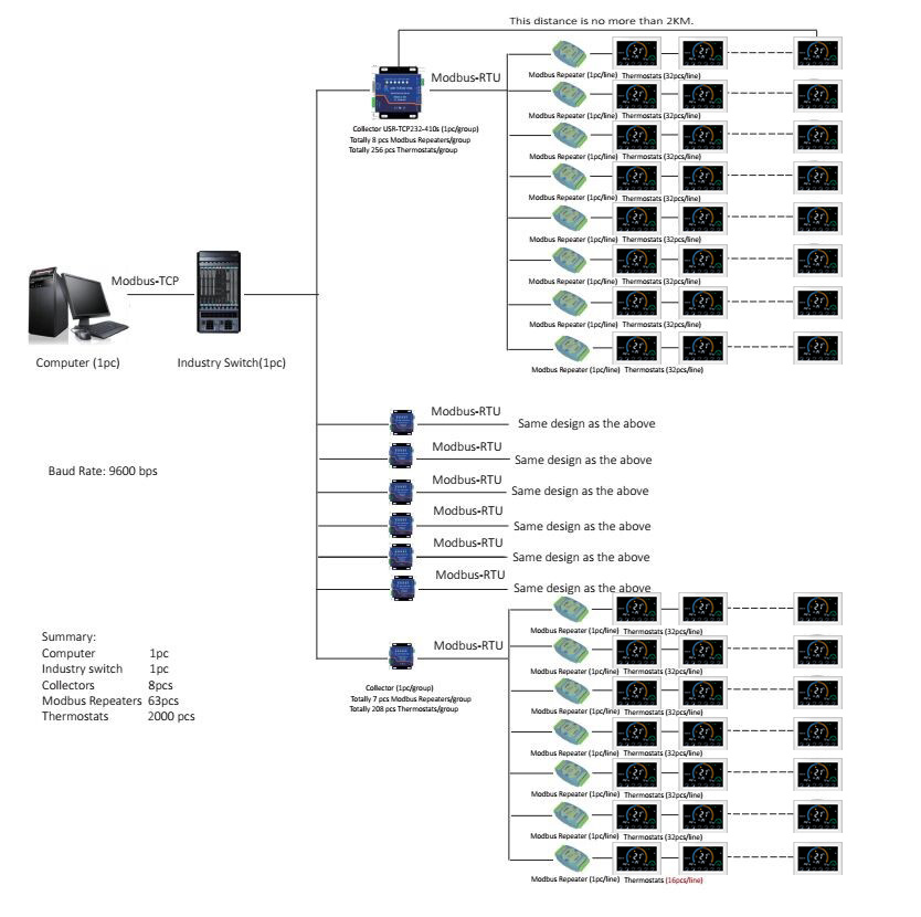
3. The maximum transmission distance can reach about 1200 meters, but the transmission rate and transmission distance are inversely proportional. Only the transmission rate below 100KB/s can achieve the maximum communication distance. If you need to transmit longer distances, you can use relays .
4. Multi-machine communication can be realized by networking on the bus, and multiple transceivers are allowed to be hung on the bus. From the perspective of the existing RS485 chip, there are drivers that can be connected to different devices such as 32, 64, 128, and 256.
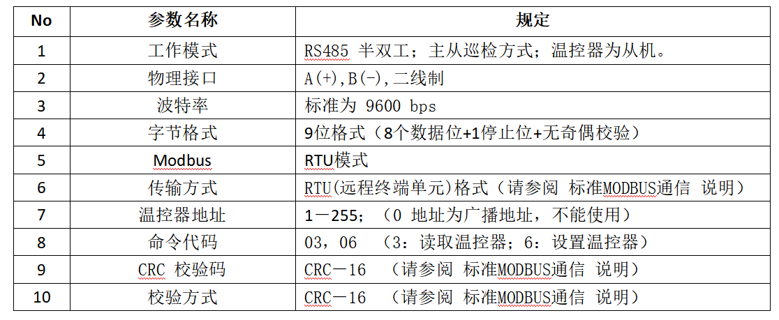
RS485 has two-wire system and four-wire system. Four-wire system can only realize point-to-point communication, which is rarely used now. The two-wire connection method is a bus topology, and a maximum of 32 nodes can be connected on the same bus. In the RS485 communication network, the master-slave communication method is generally used, that is, a master with multiple slaves.
In many cases, when connecting the RS-485 communication link, simply use a pair of twisted pairs to connect the "A" and "B" ends of each interface. Ignoring the connection of the signal ground, this connection method can work normally in many occasions, but it has buried a lot of hidden dangers for two reasons:
Common mode interference problem: The RS-485 interface uses a differential method to transmit signals, and does not need to detect signals relative to a certain reference point. The system only needs to detect the potential difference between the two lines. But people often ignore that the transceiver has a certain common-mode voltage range. The common-mode voltage range of the RS-485 transceiver is -7 to +12V. Only when the above conditions are met, the entire network can work normally. When the common mode voltage of the network line exceeds this range, it will affect the stability and reliability of communication, and even damage the interface.
EMI problem: The common mode part of the output signal of the transmission driver needs a return path. If there is no low-resistance return path (signal ground), it will return to the source in the form of radiation, and the entire bus will be like a huge antenna. Externally radiated electromagnetic waves.
[Modbus communication protocol]
The Modbus protocol is a common language applied to electronic controllers. Through this protocol, controllers can communicate with each other, controllers via a network (eg Ethernet), and devices. It has become a common industry standard. With it, control equipment produced by different manufacturers can be connected into an industrial network for centralized monitoring.
This protocol defines a message structure that a controller can recognize and use, describes the process of a controller requesting access to other devices, how to respond to requests from other devices, and how to detect and log errors. It establishes a common format for the format and content of message fields.
Modbus has the following characteristics:
1. Standard and open, users can use the Modbus protocol for free and with confidence, without paying license fees and without infringing intellectual property rights. At present, there are more than 400 manufacturers supporting Modbus, and more than 600 products supporting Modbus.
2. Modbus can support a variety of electrical interfaces, such as RS-232, RS-485, etc., and can also be transmitted on various media, such as twisted pair, optical fiber, wireless, etc.
3. The frame format of Modbus is simple, compact and easy to understand. It is easy for users to use and easy for manufacturers to develop.
1. Description of Modbus register types
1— Coil state: output port, the output state of the port can be set, and the output state of the bit can also be read
2—Discrete input state: input port, change the input state through external setting, readable but not writable
3—Holding register: some parameters set when the controller is running, readable and writable
4—Input register: some parameters obtained from external devices when the controller is running, readable but not writable
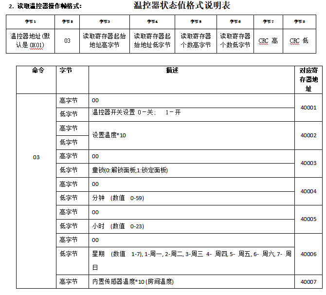
2. Modbus communication data format
A single write:
Multiple writes:
read:
3. Brief description of Modbus function code
Function code can be divided into bit operation and byte operation. The minimum unit of bit operation is Bit, and the minimum unit of byte operation is 2 bytes (Byte).
1—Bit operation command: read coil state 01H, read discrete input state 02H, write single coil 05H, write multiple coils 0FH.
2—Byte operation instructions: read save register 03H, read input register 04H, write single save register 06H, write multiple save registers 10H.
4. Modbus function code
Anterior:
Winter break is coming!
Siguiente:
Unlimited surprises, new for Christmas!
Anterior:
Winter break is coming!
Siguiente:
Unlimited surprises, new for Christmas!
推荐新闻


Búsqueda
Sobre nosotros
Productos
Centrol del Videos
Contácto
Teléfono:+86-592-6151256
Emailsales@becaenergy.com
Dirección: Room 502, 5th Floor, No. 7, Lianfa Gold Industrial Park, Tong'an District, Xiamen, China

Cuenta pública de WeChat